Centrifugal Stress Analysis of a Centrifugal Machine Using Ansys Mechanical
Learn how to evaluate centrifugal stresses in rotating components using static structural analysis in Ansys Mechanical — with theoretical validation, rotational inertia loads, and modal analysis for resonance risk assessment.
WK
Wakar Ali Mohammad Khan
May 8, 20266 min read
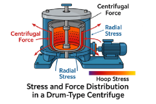
Centrifuge machines are widely used in industrial and laboratory applications to separate materials based on their density. During operation, these machines rotate at extremely high speeds, generating significant centrifugal forces. These forces act radially outward from the axis of rotation and induce stresses throughout the rotating components. Evaluating these stresses is critical for ensuring the structural integrity, safety, and performance of the system.
Analyse such stresses without explicitly simulating rotation, rotational velocity can be applied within a Static Structural analysis framework. In this approach, the part itself does not physically rotate; instead, rotational effects are represented as inertial body loads within the rotating reference frame formulation. This allows the centrifugal effects to be captured as inertial loads.
The general governing equation of motion is:
m·ẍ + c·ẋ + k·x = F(x) …(a)
For static structural analysis, the acceleration (ẍ) and velocity (ẋ) terms are neglected, simplifying the equation to:
k·x = F(x)
In this formulation, gravity, rotational velocity, and rotational acceleration are treated as inertial loads and included in the force term F(x).
Section 01Why Static Analysis?
The primary aim of this study is to evaluate stress in a component rotating at a constant angular velocity. Since the rotation is steady (no change in speed), transient effects such as acceleration and damping are not significant. Including them would unnecessarily complicate the analysis, requiring additional unknowns to be solved.
Static analysis offers a simplified yet effective solution in such cases. It avoids the computational complexity of transient analysis while still accurately capturing the stress distribution due to steady rotational effects. This approach is particularly useful in engineering practice, where quick and reliable stress estimates are often needed during design and validation stages.
Section 02Theoretical Background
The centrifugal force on a particle when it is moving with a velocity on a curve is given by:
F = ρ · ω² · r …Equ. (1)
Where:
ρ = density of the material (ton/mm³)
ω = rotational speed (rad/s)
r = radius of the disk (mm)
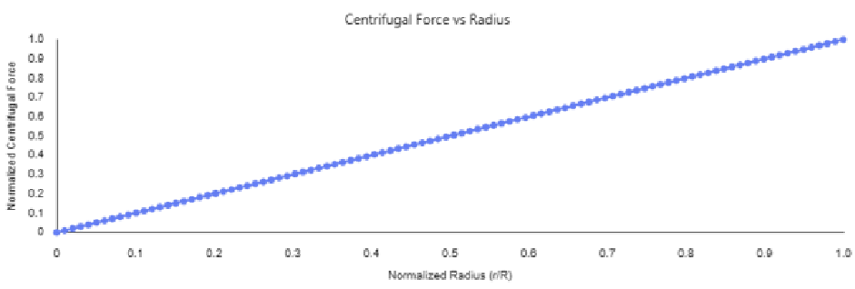
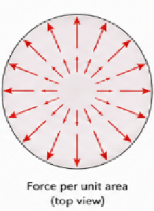
Centrifugal force vs. radius
Note: An important observation is that the centrifugal body force density increases linearly with radial distance from the axis of rotation. Therefore, elements located farther from the centre experience higher forces.
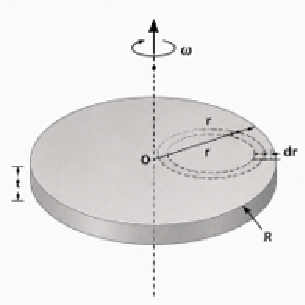
A solid homogeneous circular disk of uniform thickness (or a solid cylinder) of radius R mm, Poisson's ratio μ, and weight per unit volume ρ ton/mm³ rotates about its own axis with a uniform angular velocity of ω rad/s. At any point at distance r mm from the centre there is a radial tensile inertial stress (Roark's formula, 7th Ed., page 746).
Radial stress
σᵣ = ρ · ω² · (R² − r²) / 8 · (3 + μ) …Equ. (2)
Where:
σ = radial stress at a radius (MPa)
R = radius at which the stress is calculated (mm)
μ = Poisson's ratio
Key insight
Location (Radial)
Centrifugal force (N)
Stress (MPa)
Center
Minimum
Maximum
Outer edge
Maximum
Zero
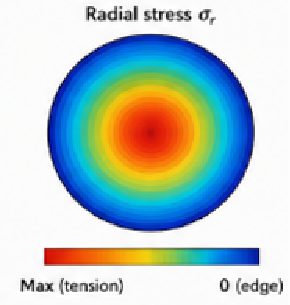
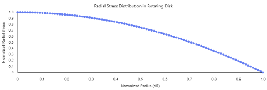
This behaviour can be interpreted physically: although the outer edge experiences the highest centrifugal force, it is free to deform outward and therefore carries no radial stress. In contrast, the centre must resist the cumulative outward pull of all material surrounding it, resulting in maximum stress at the centre.
Theoretical calculations
Verification at outer edge. Substituting r = 203 mm (outer-most) and R = 203 mm in Equ. (2):
This value shows that stresses increase as we move toward the centre.
Section 03Boundary Conditions & FEA Setup
To simulate the system in Ansys Mechanical:
A cylindrical support is applied at the shaft/motor interface to restrict motion appropriately.
Rotational velocity is applied to the rotating disk as an inertial load.
The outer diameter is kept free to deform naturally.
Points to remember:
The outer boundary must remain unconstrained to correctly represent real physical behaviour.
Radial stresses should be extracted using a cylindrical coordinate system to ensure proper directional interpretation.
Section 04Results
Results
Hand calculation
Ansys FEA
Max stress (center)
5.82 MPa
6.0 MPa
Outer edge radial stress
0 MPa
~0 MPa
Points to remember:
The FEA results show higher stress values compared to analytical calculations. This deviation is expected due to the influence of boundary conditions, geometric constraints, and numerical approximations within the simulation.
Use a cylindrical coordinate system to extract stresses radially (normal stress in the radial direction in FEA).
Section 05Modal Analysis
Setup: pre-stressed modal linked from static structural.
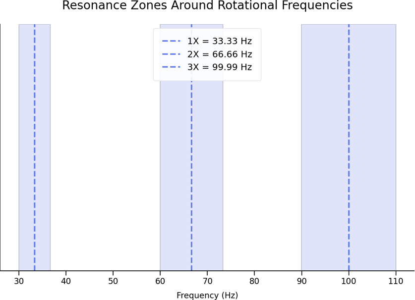
f₁ = ω / 2π = 209.44 / 2π = 33.33 Hz
Modes
Frequency
Risk zone (±10%)
1X
33.33 Hz
29.99–36.66 Hz
2X
66.66 Hz
59.99–73.33 Hz
3X
99.99 Hz
89.99–109.99 Hz
Natural frequencies within ±10% of operating harmonics should be investigated further for potential resonance risk.
Conclusion
Static structural analysis is an efficient and practical method for evaluating stresses in rotating components operating at constant angular velocity. By neglecting transient effects such as acceleration and damping, the governing equations are simplified, making the analysis more computationally efficient while still providing accurate stress predictions.
In this method, the component does not physically rotate; instead, the coordinate system rotates, allowing centrifugal effects to be modelled as inertial loads. When combined with modal analysis, this approach also enables identification of critical frequencies and potential resonance risks. Overall, static analysis serves as a powerful tool for preliminary design and validation of rotating systems, ensuring structural integrity without the need for complex transient simulations.
References: Roark's formulas for stress and strain, 7th Ed. Page 746 / Ansys mechanical user's guide-inertial loads / Engineers edge-rotating disk stress calculator