Predicting Real Structural Failures: The Critical Role of Contact Nonlinearity in Ansys Mechanical
Understand why contact nonlinear analysis is essential for accurate structural predictions — and how Ansys Mechanical's contact formulations, meshing strategies, and solver controls capture separation, sliding, and re-contact in real assemblies.
PV
Piyush Vashist
May 15, 20266 min read
Why do many structural failures occur even when stress levels appear acceptable in simulation?
The answer often lies at the interfaces between components. Bolted joints can lose preload, gears continuously change contact locations, seals may separate under pressure, and assembled parts can slide, stick, or re-contact during operation. These interface interactions significantly influence stress distribution, load transfer, deformation, vibration response, and overall structural durability.
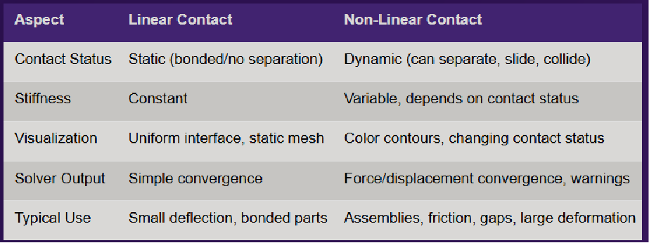
Traditional linear analysis assumes permanently connected interfaces and constant stiffness throughout loading. While suitable for many preliminary studies, this assumption often fails to represent how real assemblies behave in service.
Contact nonlinear analysis addresses this challenge by accurately modelling separation, sliding, friction, sticking, and re-contact between interacting surfaces. By capturing realistic interface behaviour, engineers can predict failure mechanisms earlier, improve design confidence, and reduce dependence on costly physical testing.
Section 01Why Contact Nonlinearity Matters
Contact nonlinearity occurs whenever the interaction between two surfaces changes during loading. Common behaviours include:
Opening and closing of interfaces
Sliding due to friction
Separation and re-contact
Local sticking behaviour
These changing contact conditions continuously alter the stiffness and load path of a structure.
Consider a bolted flange exposed to thermal cycling. A linear analysis may predict a stable connection, while the actual assembly experiences preload loss, local separation, and stress redistribution. Similarly, gear systems constantly undergo changing contact regions that influence load transfer and wear characteristics.
Ignoring such effects can lead to:
Underpredicted stresses
Incorrect deformation behaviour
Unrealistic stiffness estimation
Failure-critical regions being overlooked
As products become lighter, more optimized, and increasingly performance-driven, accurately representing interface behaviour has become essential for reliable engineering design. Realistic contact modelling often reveals stress redistribution that linear analysis cannot capture.
Realistic contact modelling often reveals stress redistribution that linear analysis cannot capture.
When Linear Analysis Is Not Enough
If your design contains any of the following, contact nonlinearity should be strongly considered:
Bolted joints
Press fits
Bearings
Gaskets and seals
Gear contacts
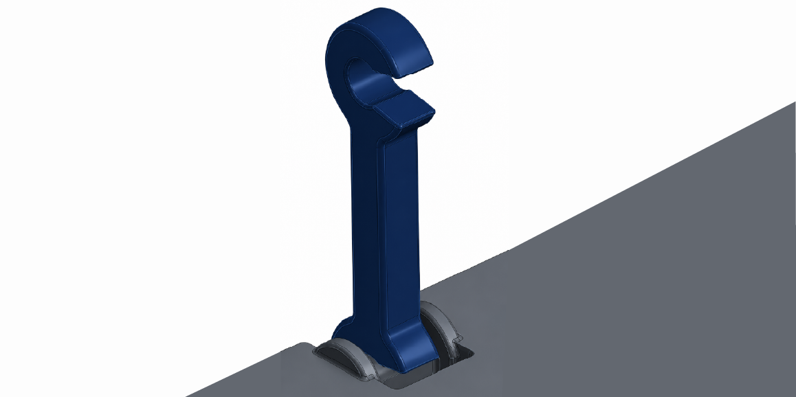
Snap-fit assemblies
Impact-loaded structures
In these applications, interface behaviour often governs structural performance and reliability more than the material itself.
Section 02Contact Types in Ansys Mechanical
Ansys Mechanical provides several contact formulations to represent different physical interactions between components.
Contact Type
Description
Typical Applications
Bonded
No sliding or separation; surfaces behave as glued
Welded joints, adhesives, rigid assemblies
Frictional
Separation and sliding with friction
Bolted joints, brake systems
Frictionless
Separation and frictionless sliding allowed
Bearings, assembly interfaces
No Separation
Sliding allowed, separation prevented
Sliding plates, wiper systems
Rough
Separation allowed, no sliding
Press fits, constrained joints
Bonded Initial
Maintains initial contact state
Preassembled structures
No Separation – Penetration Only
Initial penetration allowed, no separation
Preloaded interfaces
Selecting the appropriate contact type is critical for achieving realistic simulation results and ensuring physical behaviour is accurately represented.
Section 03Workflow in Ansys Mechanical
1. Geometry Preparation
Successful nonlinear contact analysis begins with a clean and well-prepared geometry. Recommended preparation steps include:
Removing unnecessary small features
Eliminating sliver surfaces
Ensuring proper alignment of contact regions
Simplifying geometry where possible
Good geometry preparation significantly improves solution stability and convergence.
2. Contact Definition
After geometry preparation, contact and target surfaces are defined to represent physical interfaces within the assembly. Engineers typically:
Define contact behaviour
Assign friction coefficients
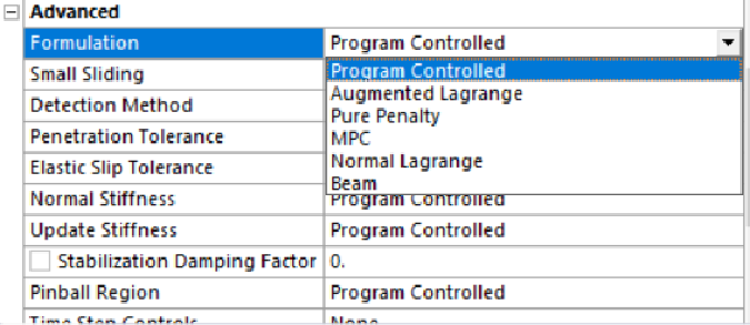
Select appropriate contact algorithms
Common contact algorithms include:
Augmented Lagrange
Penalty Method
MPC Contact
Among these, the Augmented Lagrange formulation is widely used because it provides a strong balance between accuracy and numerical stability.
3. Mesh Considerations
Mesh quality plays a major role in contact accuracy. Best practices include:
Refining the mesh near contact regions
Maintaining acceptable aspect ratios
Minimizing skewness
Using contact sizing where necessary
Poor mesh quality may result in:
Excessive penetration
Stress oscillations
Convergence difficulties
Inaccurate contact pressure predictions
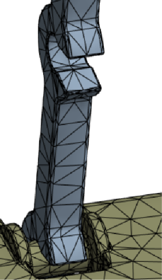
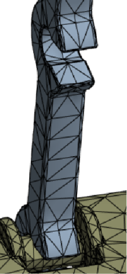
A well-refined contact mesh often delivers more reliable results without significantly increasing computational cost.
With contact sizingWithout contact sizing
4. Solver Controls & Results
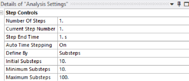
Since contact conditions continuously evolve throughout loading, appropriate nonlinear solver settings are essential. Recommended practices include:
Automatic time stepping
Smaller initial substeps
Large deformation settings when required
Convergence monitoring throughout the solution
Step controls for a nonlinear contact solution
After solving, engineers typically evaluate:
Equivalent stress
Contact pressure
Penetration
Sliding distance
Contact status
These outputs provide valuable insight into interface behaviour and help identify potential failure locations.
Section 04Industrial Applications
Contact nonlinear analysis is widely used in industries where interface behaviour directly affects performance and reliability. Typical applications include:
Bolted joint analysis
Gasket and seal evaluation
Gear contact analysis
Bearing simulations
Snap-fit assemblies
Impact and drop testing
By accurately representing surface interactions, engineers can reduce physical prototyping, improve product reliability, and identify failure-prone regions much earlier in the development process.
Conclusion
Many structural failures originate not from material limitations, but from the way components interact with one another.
Contact nonlinearity enables engineers to capture realistic behaviours such as separation, sliding, friction, sticking, and load redistribution—phenomena that are often responsible for critical failure mechanisms. By moving beyond idealized assumptions, engineers gain a deeper understanding of how assemblies behave under real operating conditions.
Modern simulation tools such as Ansys Mechanical provide robust capabilities for solving complex contact problems with high accuracy and efficiency. As products continue to become lighter, smarter, and more optimized, contact nonlinear analysis will remain a critical tool for predicting performance, reducing development costs, and improving design reliability before the first prototype is ever built.